Underslung Tank Fitting.
Underslung tank fitting
VIDEO TIPS >> CLICK
How to choose and install underslung vapor LPG tank
- Before you buy and tooling
- Safety, Euro-tunnel restrictions
- Installation of the tank
- Mounting the frame
- Tank positioning
- Securing the straps
- Level indicator
- Filling point
- Filling hose
- Pressure regulator
- Connecting appliances
- Filling with gas
- European adapters
Before you buy
Campervan conversion is a complex and challenging task. Even with a good plan changes are unavoidable, so it is good to consider all options before buying an underslung tank. Think of clean and dirty water tanks, spare wheel and ideal routing for gas lines.
When selecting place for tank check if:
- Installed tank does not reduce ground clearance
- It is at least 4 inches from exhaust pipe
- It does not block handbrake cables
- The floor above is stiff enough
- There is access from the inside for cradle bolts
- There is easy access to silver valve box
- The filling point would be on the same side of the vehicle as the tank
- The movement of suspension won't be interfering with piping.
Carefully measure space available, you can build a maquete of tank from cardboard. The cradle adds to more than 1 cm of total height. Check which style of filling point suits you the best. Roughly estimate the length of gas pipes and add a few meters as a safety margin.
Tools required
Standard set of basic tools is required:
- Drill, drill bits: 10mm, 8mm
- Allen key 5mm
- Spanner sizes from 10mm to 24mm
- 8mm, 17mm sockets
- Hole saw 70mm for recessed filling point
- Marker pen
- Screwdrivers
- Soldering iron and solder wire for level sensor
Safety features
The tank, filling point and high pressure pipings are made according to United Nations Regulation No. 67 which describes specification and requirements for LPG related automotive parts.
The pressure regulation conforms British and European standards 16129:2013.
The rest of the parts including low pressure connectors are made of gas-safe brass and they are industry standard parts.
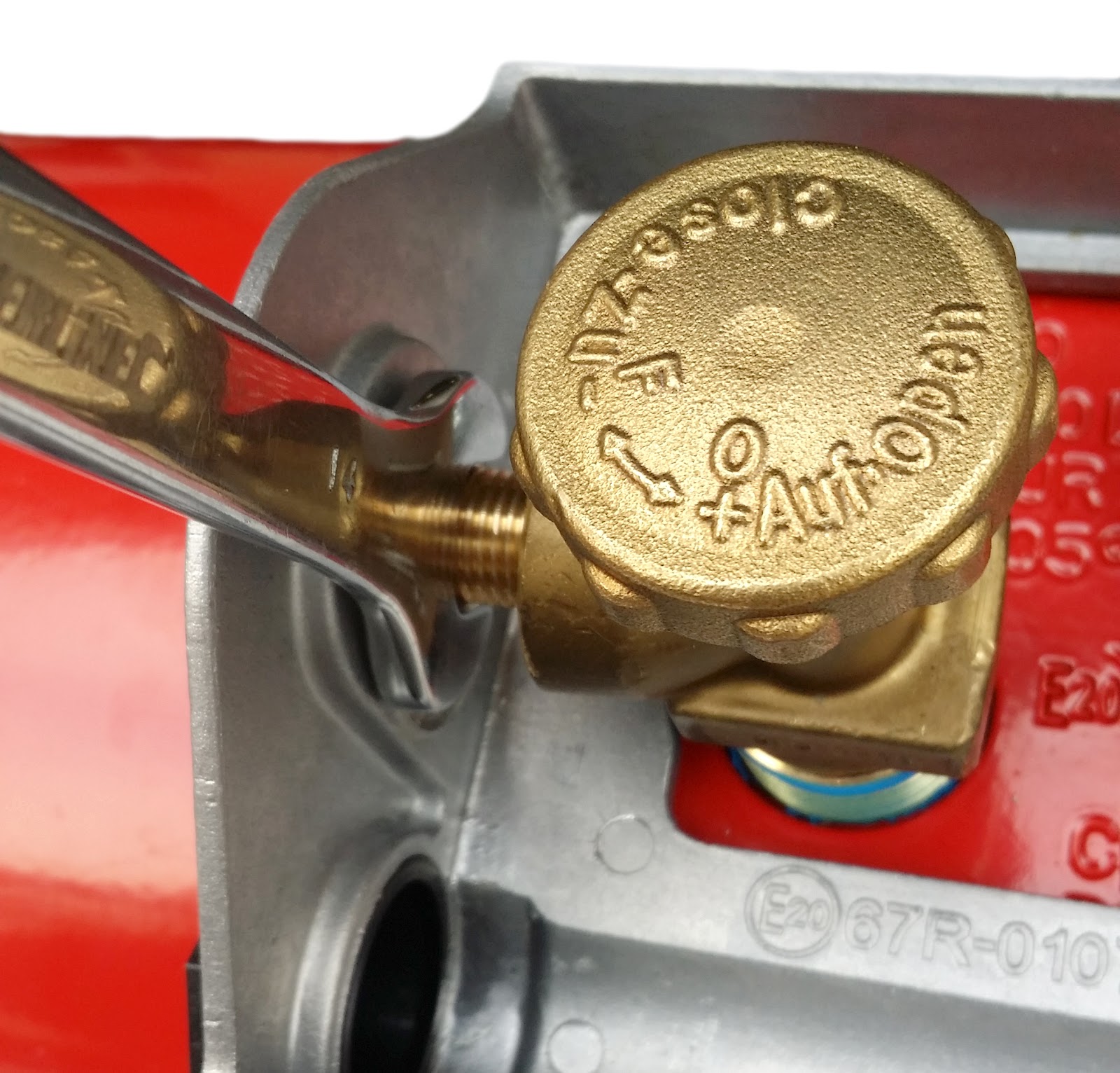
The tank itself is fully fitted with following valves:
- Outlet valve with manual knob, inner thread ¼” NPT
- 80% cut off valve (OPD)- the filling valve prevents overfilling and shuts the inlet when 80% gas level is reached; non-return valve - in case of physical damage of filler hose the gas accumulated in the hose is released;
- over pressure relief valve (PRV) - in case of sudden pressure increase (over 27 bar) the excess gas is released to the environment;
- Level indicator - mechanical level indicator with float inside.
Eurotunnel restrictions
Red vapour tanks are allowed in Eurotunnel.
If travelling with a campervan, caravan or any other vehicle fitted with cooking facilities, any flammable gas container must be declared when asked and will be checked at the appropriate checkpoint by Eurotunnel Le Shuttle.
Flammable gas containers may be transported with the following restrictions:
- For fixed containers (tanks): Maximum of 47kg per container and no more than 50kg per Vehicle if more than 1 container.
- Fixed containers must be no more than 80% full. The capacity of the container will be checked by Eurotunnel staff.
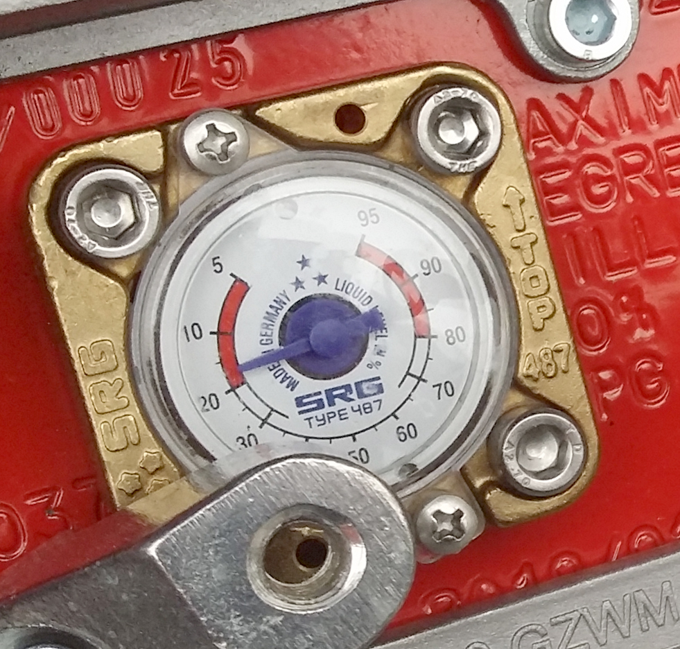
Level indicator
How does it work?
Inside of the tank there is a float which rotates magnetic disk when the level changes. Magnetic field is transferred to the outside as the brass is not magnetic, so the gauge works like a compass.
Livello indicator
The Livello gauge system includes electronic level sender and level indicator with switch and 9 LED.
Installation of gauge
- Loosen the cover mounting point using 5mm Allen key

- Remove the level indicator
- Install level sender - secure it by using the other set of holes

Installation of indicator
Find an easy to access place for level indicator.
- Drill 8mm hole
- Connect the red wire to ignition live or fused battery connector. The indicator draws power only when it is on.
- Connect black cable to ground point
- Extend and connect level gauge - black to black, green (signal) to green.

Tank positioning
The tank has to be positioned at a certain angle. This is very important for few reasons:
- gas outlet pipe cannot be submerged in liquid gas,
- 80% cut off valve float won't shut off gas during refiling which may cause dangerous overfilling.
To properly position the tank please check all following:
- At filler valve the TOP indicator is on the top
- The leveling bumps (or sticker) points up and the symbol is located at 3o’clock position
- The valves are located at 105 degree (3:30 o’clock)
Securing the tank to the chassis
Installation of filling point
In the UK the standard Autogas fitting is called Bayonet. The filling point is equipped with a non return valve, so when refilling is finished the gas is trapped inside of the filling point hose.
There are few different filling point styles:
- Round box with recessed filling point. It requires a 70mm hole in the body and about 10cm clearance behind the panel. This is the most common solution.
- Filling point on bracket. Bracket can be bolted to the body or chassis using a self tapping screw or you can reuse i.e bumper fitting. The most universal and the easiest to install.
All the filling points should be installed outside of the cabin, so in case of leak the gases are not accumulated in the living space.
Round box
- Find the spot, make sure that there is enough clearance (about 10cm) behind the spot, carefully drill 70mm hole. Clean the edges with a file.

2. Cut two small indents with a sharp knife or narrow file. This is to prevent box from rotating. The indents should be in the highest and lowest position opposite to each other.
3. Take the filling point and put 4 small screws in place

4. Put the filling point inside the box. The lugs on the filling point should be on the sides, keys for indents at top and bottom.
5. Install the screws and secure the with nuts - 8mm spanner required.
6. Put the assembly through the hole, make sure lugs are on the side and hose fitting is on the desired side. Install the cup on the other side, make sure that the rubber gasket is in place. You can put a small amount of vaseline to keep it in place.
7. In case of installing a filling point on thicker (over 5mm) panel, use longer self tapping screws. Make sure they are not coming out on the other side.

8. Install and tighten the hose / hose adapter. Make sure the connection is very tight. You can apply a little bit of Teflon tape, but it is not required.

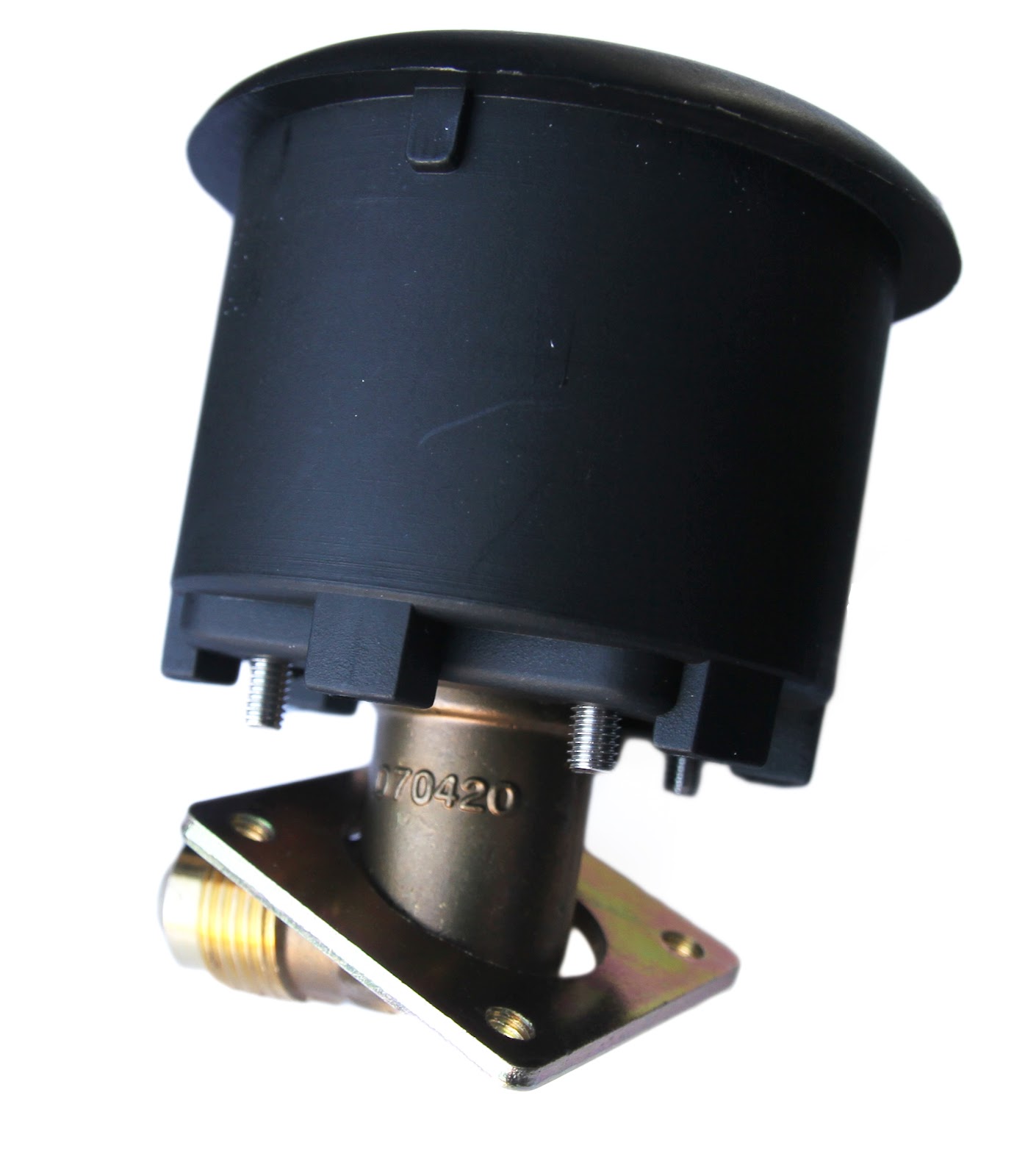
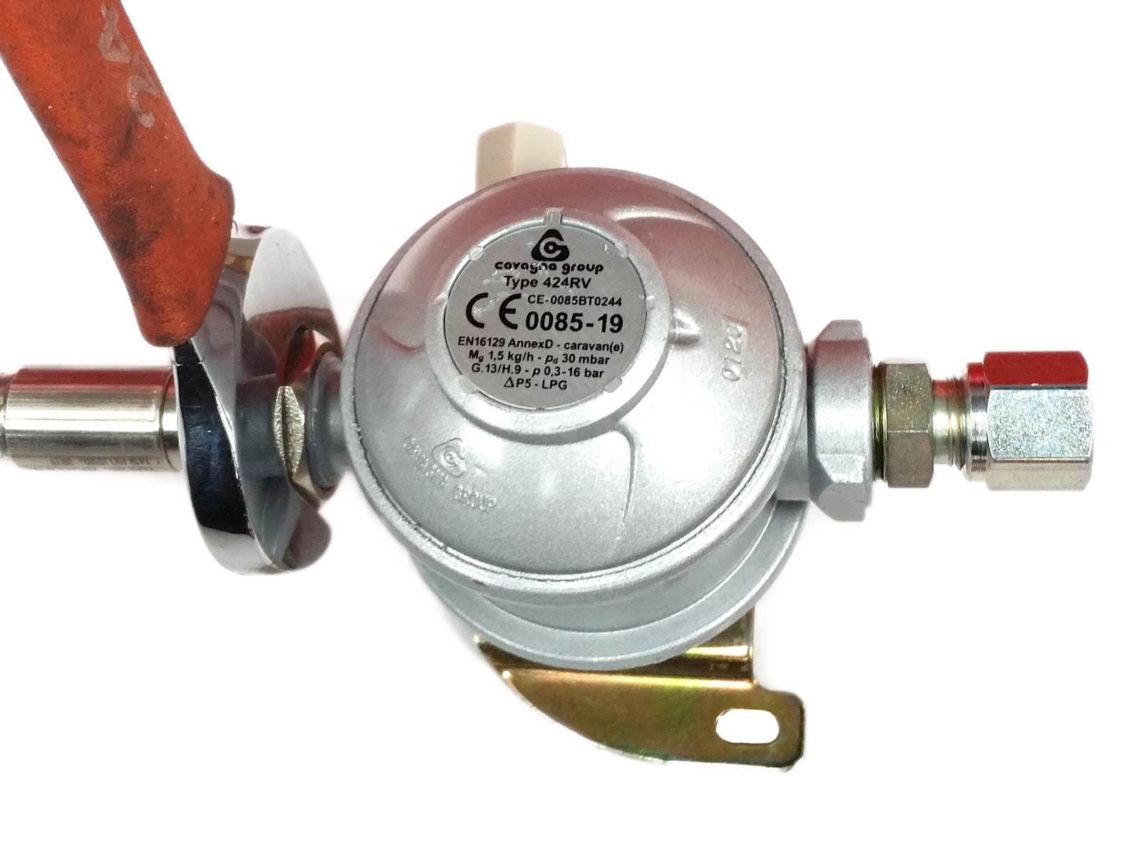
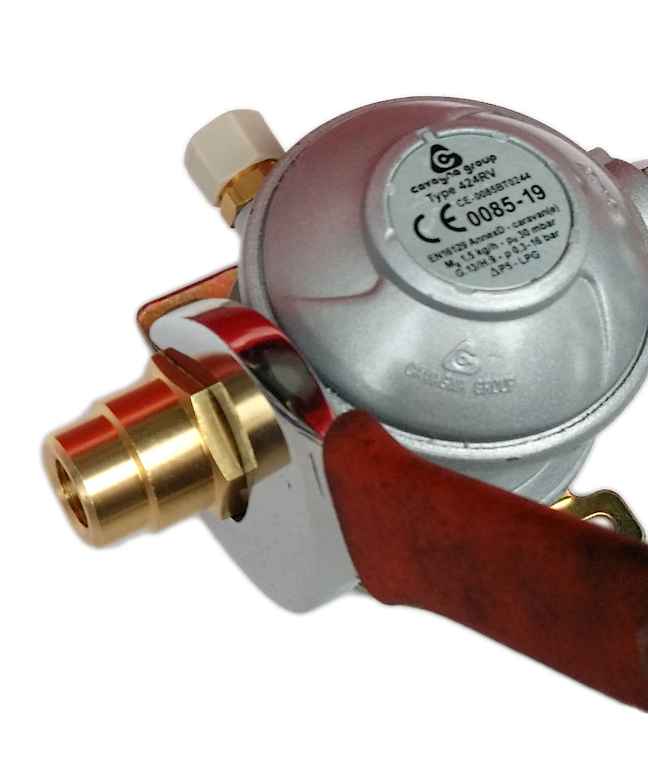
Installation of pressure regulator
The gas is stored in the tank under high pressure in liquid form. The pressure is variable (4-12 bar) and it highly depends on:
- Gas temperature - ambient temperature (higher the temperature higher pressure,
- Fill level (higher the level higher pressure),
- Type of gas (propane - higher pressure).
All gas camping equipment used in Europe and produced after 2003 should be compatible with propane with supply pressure of 30mBar.
In two stage regulators the pressure is lowered down in two steps, to 600mBar and then to 30mBar. Two stage regulators guarantee that the outlet pressure is stable and it does not depend on level and temperature of the gas stored in the tank.
The regulator itself should be installed above the tank, this is to ensure that tiny droplets of gas cannot reach the regulator - the evaporation process should be taken in the tank.
The standard connections are:
- Gas inlet: M20 (W20)
- Gas outlet: 8mm copper pipe or 10mm stainless steel pipe.
The 10mm pipe is used in factory fitted conversions and it requires special equipment and high experience. 8mm copper pipe is much easier to work with and it still provides enough throughput.
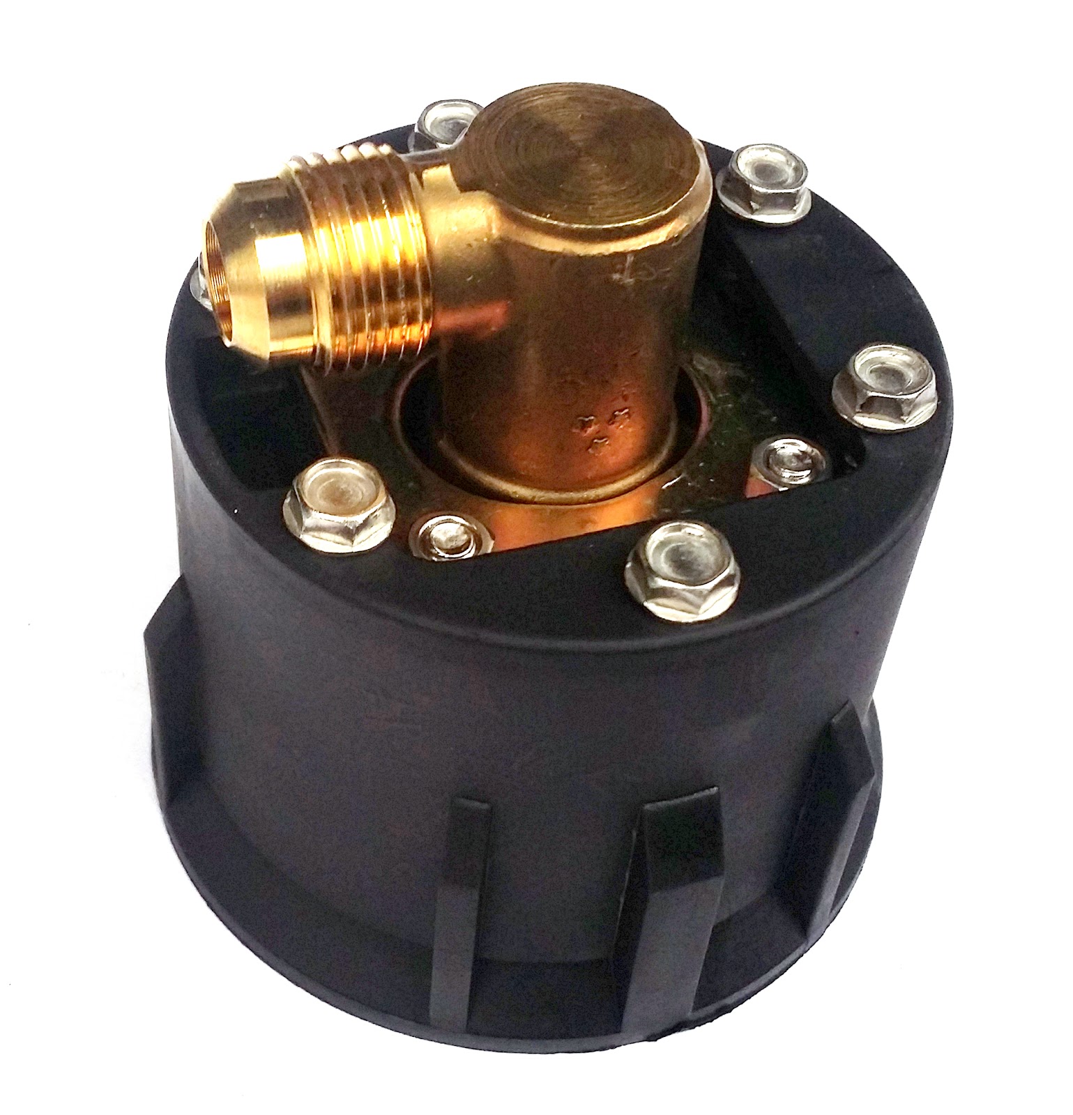
The regulator can be connected to the gas tank:
- Using stainless steel pigtail (preferred) or rubber pigtail,
- Using 8mm copper pipe in PVC coating.
If the vehicle is equipped with a factory fitted gas regulator there is a possibility of connecting it to the tank using a long 8mm copper pipe.
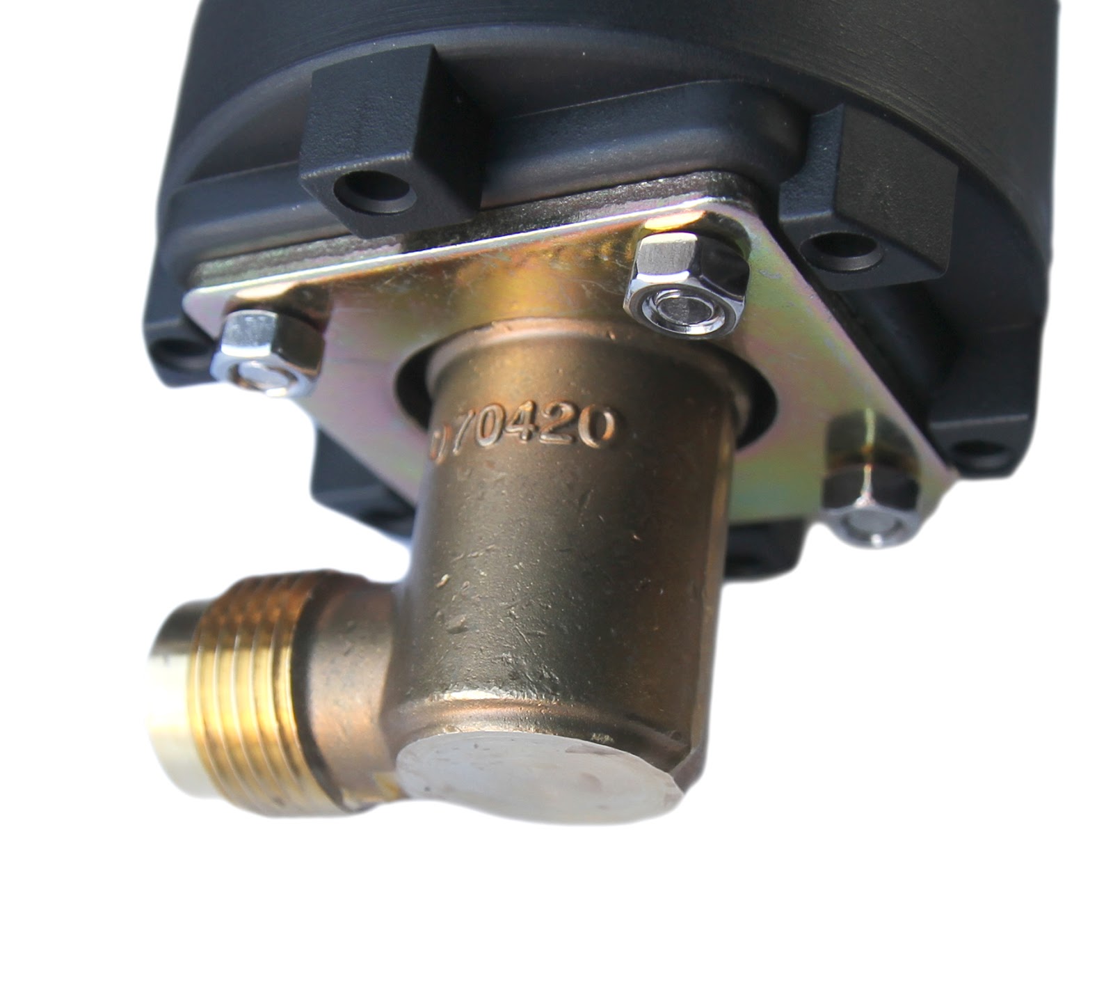
General rules for regulator placement:
- Located above the tank,
- Breather (ventilation) hole downwards,
- Test point easily accessible (white nut on the side),
- Insulated from dirt, rain, mud, etc.
- Enough space for inlet / outlet connections.
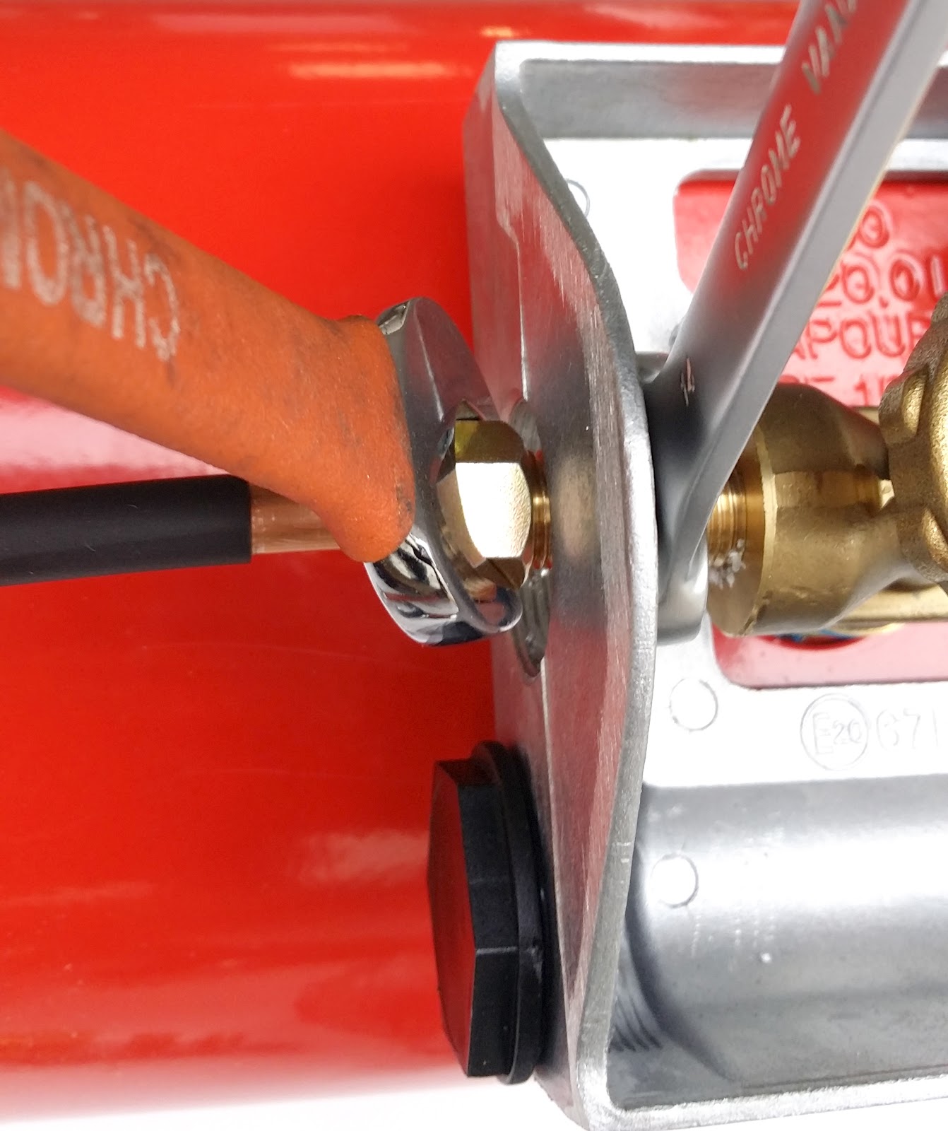
Installation of regulator using pigtail
If you're chosen the stainless steel pigtail to connect the regulator with the tank you might have a problem with pushing the bigger pigtail nut through the aluminum box.
The good news is that you don't have to purchase any additional parts and you're not missing anything .
Step 1.
Loosen 4x allen key bolts holding the base of the aluminium cover. (marked in blue on the photo)
Step 2.
Push the smaller end of the pigtail from the inside - out direction

Step 3.
Attach the big pigtail nut to the valve.

Step 4.
Reattach the base of the aluminium cover using 4x allen key bolts.

Step 5.
Attach the smaller end of the pigtail to the regulator
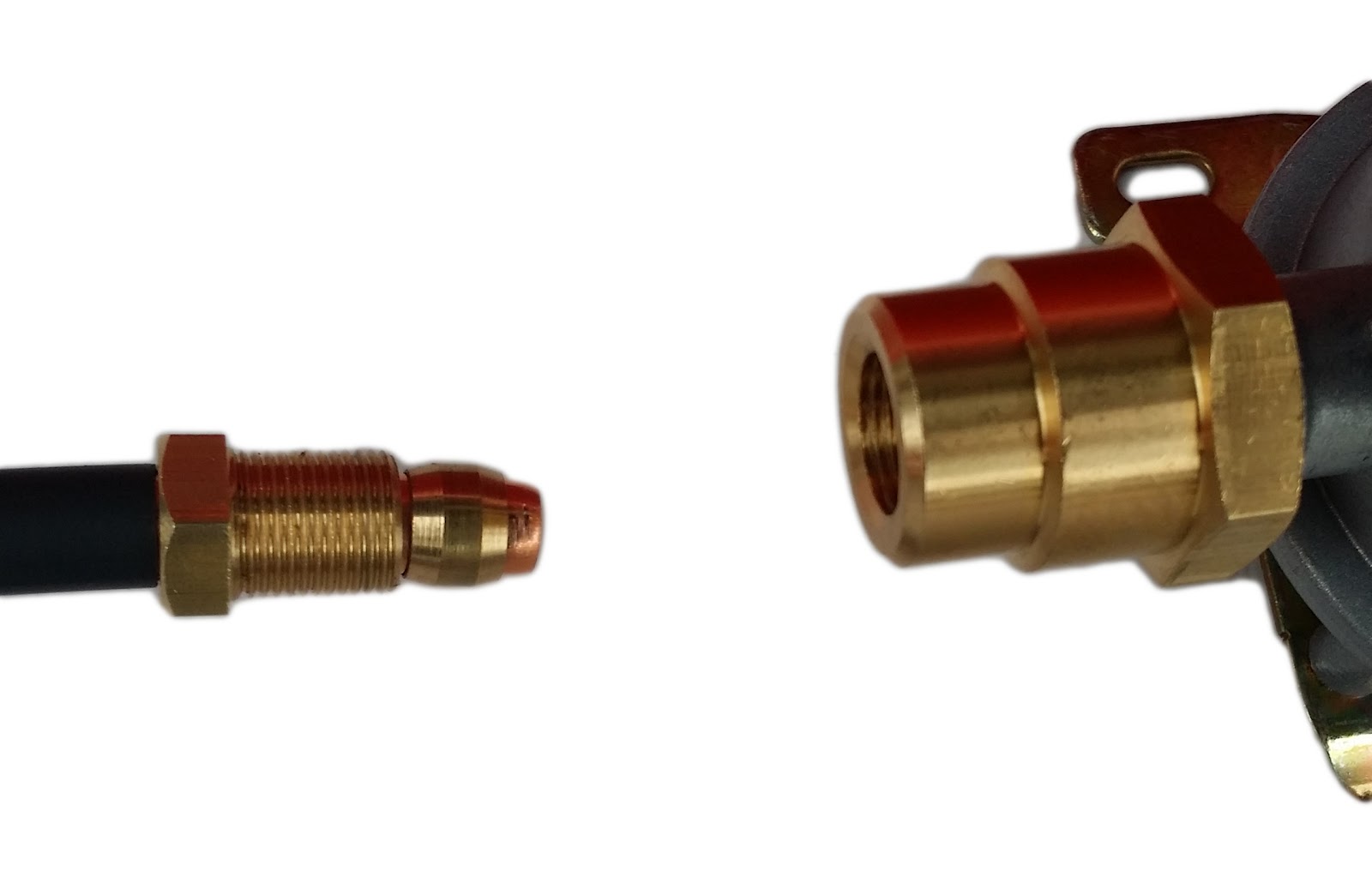
Route copper pipe, trim one inch of PVC insulation. Put nut and olive on the copper pipe.

4. Tighten the nut (17mm spanner) whilst pushing the copper pipe towards the regulator. This is to ensure that olive is compressed over pipe. Once the nut is briefly tightened, hold the regulator using a 22mm spanner and fully tighten the nut.
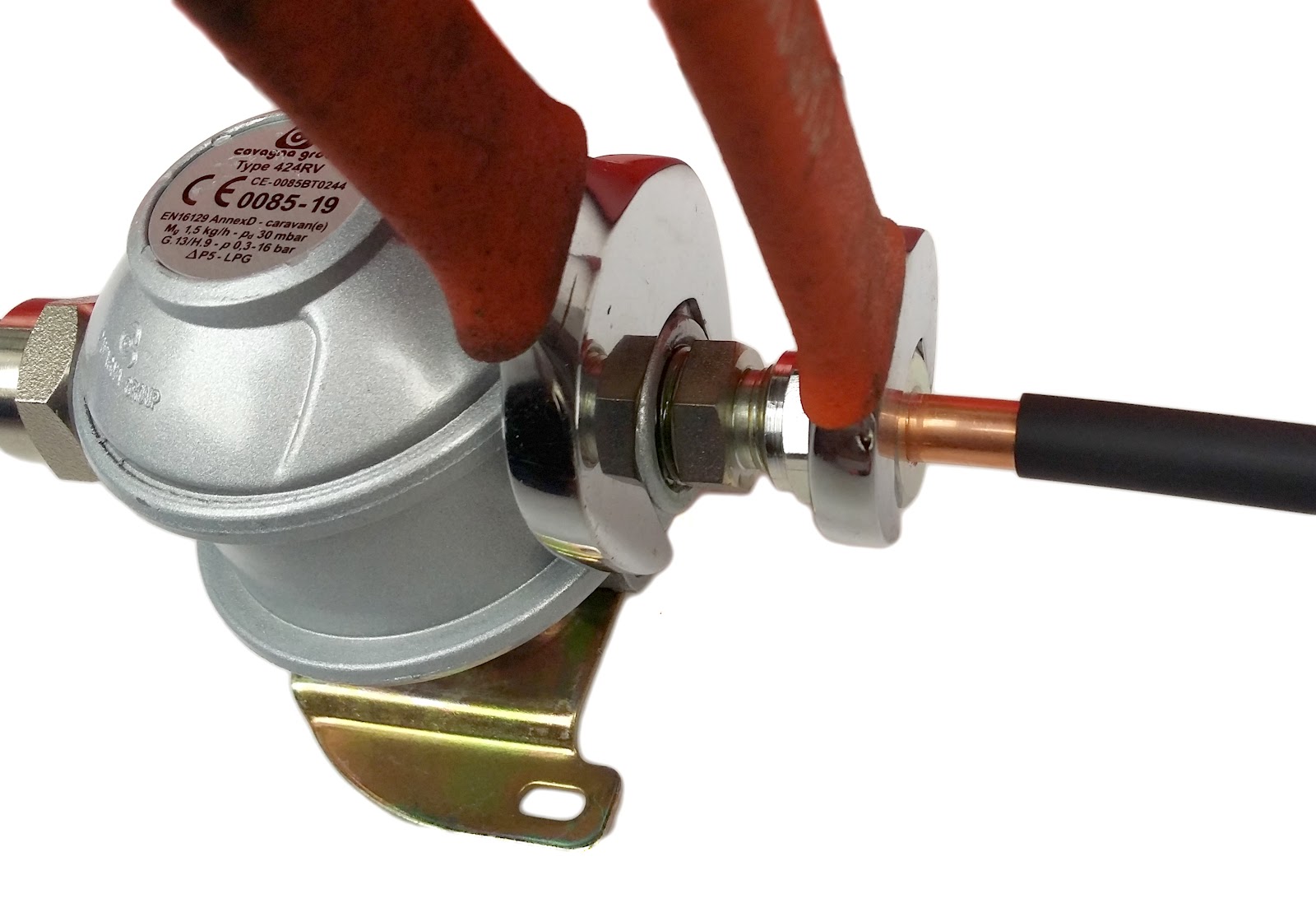
5. Secure the regulator using ie. self tapping screws. Put sleeving over copper pipe, use P clips to mount the pipe to the floor.
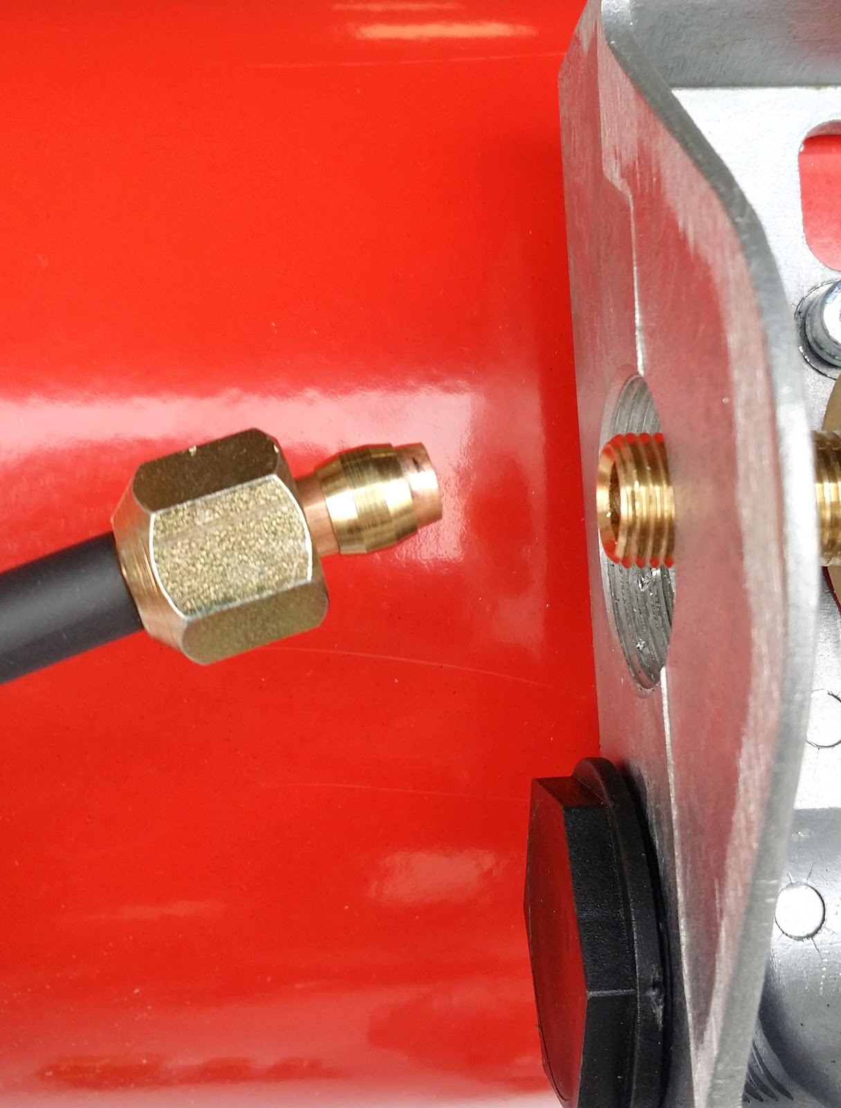
Installation of regulator using 8mm copper pipe
The regulator can also be connected to the tank using an 8mm copper pipe. If you want to reuse your existing propane regulator (i.e. located in gas locker) you can connect it to the tank using copper pipe.
The tank is supplied with a nut connector, which has to be removed in case of using compression copper fitting.
You will also need M20 to 8mm pipe connector.
- Remove nut fitting using a 14mm spanner, clean white residue.
- Screw in compression fitting nipple using a 14mm spanner. This is tampered self-sealing thread, however small amount of Teflon tape can be used

-
Remove one inch of PVC cover from 8mm copper pipe, put nut and olive
-
Tighten the nut whilst pushing the pipe towards valve, hold the nipple and prevent it’s overtightening
-
Route the pipe, screw in M20 adapter to the regulator - make sure the rubber seal is in place.
-
Remove one inch of PVC cover from 8mm copper pipe, put nut and olive
-
Tighten the nut whilst pushing the pipe towards valve, hold the nut to prevent over tightening

European adapters
If you are planning an overseas journey, you will need adaptors for your filling point as only a few countries use British standard.
The adapters are made of a single piece of brass and they easily screw into the internal thread of British Bayonet filling point. They do not require additional tools, they can be screwed in using bare hands.
Set of three different adapters will make sure that you will be able to refill your tank anywhere in Europe.